PREFACE
Scope of this Guide
Role of the Grain Division Standards, Abrasive Microgrits and Analytical Procedures Committee
TYPES OF ABRASIVES
Naturally Occurring vs. Manufactured
Manufactured Abrasives
1. Chemical Composition
A. Aluminum Oxide-Based
B. Silicon Carbide
C. Other Manufactured Abrasives
2. Shapes
3. Heat Treatments
4. Surface Treatments
MANUFACTURE OF ABRASIVES:
Most Common Methods
Furnacing Aluminum Oxide
Furnacing Silicon Carbide
Size reduction
Size Classification
Sintering
CHARACTERIZATION OF ABRASIVES
How Big Is This Particle?
Methods of Measurement
Screen Sizing Using Test Sieves
Calibration of Test Sieves
Microgrits: Sedimentation
Microgrits: Electrical Resistance Method
Other Methods of Measurement
Variability Within and Between Testing Methods
NATIONAL AND INTERNATIONAL SIZE STANDARDS
MACROGRITS
MICROGRITS
SUPERABRASIVES
APPENDICES
I. Glossary
II. List of standards supported by the UAMA Standards Committee
III. Standard Sands for the Abrasives Industry
Preface
Purpose and Scope
This guide is intended as a non-technical introduction to the types of abrasives commonly manufactured and sold, both to industry for further processing and directly to the end user. It is hoped it will be useful as an introduction for the novice, a ready reference for the experienced user, and a source of broader information for those who are familiar with only a part of the information provided. Obviously, materials scientists have spent entire careers studying different aspects of abrasives, and only the most commonly used of these areas can be briefly touched on here. It is anticipated that this guide will be included on the United Abrasives Manufacturers Association (UAMA) web-site, and key topics here will be linked to more in-depth discussions elsewhere on the site or elsewhere on-line. This guide includes a glossary of terms commonly used. When mentioned in the text, these terms will appear in italics.Role of the Grain Division Standards, Abrasive Microgrits and Analytical Procedures Committee (Standards Committee)
The Standards Committee is tasked with reviewing and updating national standards relating to abrasive grain. They also serve as the industry link to bodies such as the American Society for Testing and Materials (ASTM) which develop and issue standards in which the abrasives industry is a stakeholder, such as ASTM Specification E-11, which governs the manufacture and classification of test sieves. Additionally, the committee maintains a supply of "standard sands" (see below), which are used to verify particle size measurement equipment. Finally, the committee maintains ties to partner companies in various industries, such as sieve manufacturers, manufacturers of various types of testing equipment (such as magnetic analyzers), and manufacturers of particle size measurement equipment, to help member companies keep up with new technology and methods of particle characterization.Common Types of Manufactured Abrasives
Naturally Occurring vs. Manufactured Abrasives
Throughout history, humans have used as abrasives everything from beach sand to walnut shells to paper bags. This section covers some of the most widely used types of manufactured abrasives. By manufactured abrasives, we mean primarily those materials that are created through a manufacturing process as opposed to being mined from the earth. Some naturally occurring materials are also produced artificially (such as aluminum oxide and diamond), so it is impossible to draw a hard and fast line between these two categories. Additionally, naturally occurring abrasives are often used in the same applications as manufactured abrasives. Thus, some naturally-occurring abrasives are mentioned briefly and listed in the glossary.
Widely-used naturally occurring abrasives include garnet, cerium oxide, flint, emery, corundum (aluminum oxide), and diamond. These materials may have varying characteristics and chemical compositions depending on the specific geological source. Manufactured versions of these materials are usually more consistent in chemical composition and other characteristics.
Manufactured Abrasives
Abrasives can be distinguished in a variety of ways- their hardness, color, chemical composition, crystal shape, and friability, to name but a few. Since the chemical composition- that is, the type of material- determines many of the other characteristics, we use that as the primary means of distinguishing one type of abrasive from another.
1. Chemical Composition
a. Alumina Based ( Aluminum Oxide, Al2O3) (9.0 on Mohs hardness scale)
White Fused Aluminum Oxide - High chemical purity (>99% Al2O3); generally used for applications where high purity is important (medical, dental or other industrial uses); generally softer or more friable than other abrasives; used in grinding applications where a more friable product is desired. Granules typically are blocky shaped (see below, Shape), with an aspect ratio of approximately 1:1 to 3:1.
White Calcined Aluminum Oxide - High purity aluminum oxide (>99.5% Al2O3), manufactured by growing individual crystals from seed crystals at high temperature. Crystals are hexagonal platelet shaped with an aspect ratio of 5:1. Used in a variety of lapping, buffing and polishing applications, incorporated into bars and pads, and used in ceramics.
Aluminum Oxide with Chrome - White Aluminum Oxide fused with Cr2O3 to enhance grinding; a pink abrasive used in grinding applications requiring slightly more toughness than White Fused Aluminum Oxide.
Brown Fused Aluminum Oxide - Abrasive with a content of 2-4% TiO2 to further enhance toughness; the "workhorse" of the industry; used in a wide variety of uses including Bonded, Coated, Refractory and Industrial markets; probably the most widely used abrasive.
Low Titania Brown Fused Aluminum Oxide - Abrasive with a content of 1-2% TiO2 to enhance toughness of the grain; generally used in Bonded or Coated applications requiring an abrasive slightly tougher than White Aluminum Oxide.
Zirconia-Alumina - The toughest of the alumina based products; used in Bonded, Coated and Sandblasting applications requiring an extra tough abrasive.
Hydrated Alumina - Aluminum oxide with water chemically bonded to the alumina. Crystals are small (typically 1 mm or less in size) and very soft; typically used for fine polishing applications and as a raw material for ceramics.
Ceramic Aluminum Oxide - A high-purity fine-grained alumina obtained from sintering dispersed colloidal alumina. This provides a tough product primarily used for precision grinding of steels and hard alloys.
b. Silicon Carbide (SiC) (9.3 on Mohs hardness scale) -
Silicon Carbide is a man-made abrasive material formed by a series of vapor-phase reactions of carbon and silicon dioxide at high temperature in an Acheson furnace. Alpha phase silicon carbide, in the form of hexagonally shaped platelets, is the most common form observed in the abrasives and refractories industries. The character of alpha silicon carbide is dependent on a number of factors such as purity of raw materials used in the Acheson furnace, and the reaction time and temperature. (see below, p. 9, Furnacing Silicon Carbide.)
Green Silicon Carbide - The highest purity Silicon Carbide manufactured; typically containing 99% or greater SiC; generally used in grinding wheels for particular grinding properties or in industrial applications requiring a high purity SiC (coatings); generally more friable than black SiC.
Black Silicon Carbide - Lower purity (95-98%), tougher Silicon Carbide; generally used in Bonded, Coated, Refractory and Industrial markets for a wide variety of applications.
c. Other Manufactured Abrasives -
Including Boron Carbide (B4C), Cubic Boron Nitride (CBN), and Diamond; used for special applications requiring very hard materials for grinding and polishing. CBN and Diamond are also known as "Superabrasives."
2. Shapes
Particle shape affects the performance of the abrasive in a variety of ways, such as the rate of stock removal and level of subsurface damage. Some specialty applications require unusual shapes. For fused alumina and many other abrasives (such as silicon carbide), the aspect ratio (length to width) is a primary descriptor of shape. For others, the aspect ratio is irrelevant or misleading. Thus, fused aluminum oxide tends to have one long dimension and two smaller, roughly equal dimensions; i.e., the thickness is roughly equal to the width. Calcined alumina tends to have two long dimensions and one much smaller one; i.e. the length and width are roughly equal, but the thickness is about one-fifth the length. (For calcined alumina, this ratio, length to thickness, is often referred to as the aspect ratio). For more exotic shapes, aspect ratio may vary with the size of the particle and thus can only be given as a range.
a. Blocky Shape (High Bulk density) - The abrasive grain is "rounded" by abrading equipment to remove very sharp, weak grain. Depending on application, the grain shape can vary from "mulled" to blocky with sharp edges. The blocky shape enhances toughness and bulk density of the grain. Applications include tougher grinding or sanding applications, longer life for sandblasting and increased density for refractory or ceramic applications. Aspect ratio is approximately 1:1. (See Figure 1)
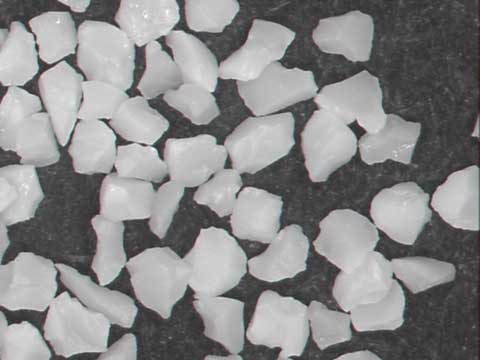
Figure 1
b. Blocky Shape (Medium Bulk density) - The abrasive grain is shaped to yield particles which are sharp but do not contain weak, platey or needlelike particles. Uses include general grinding, sanding, sandblasting and refractory applications. Aspect ratio is approximatley up to 1.5:1. (See Figure 2.)
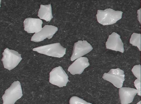
Figure 2
c. Sharp Shape (Low Bulk density) - Abrasive grain that has been specially crushed to yield very sharp grain. This is generally required by the Coated abrasives industry and some grinding wheel applications to produce an aggressive, fast cutting product. Aspect ratio ranges from 1.5:1->3:1. (See Figure 3.)
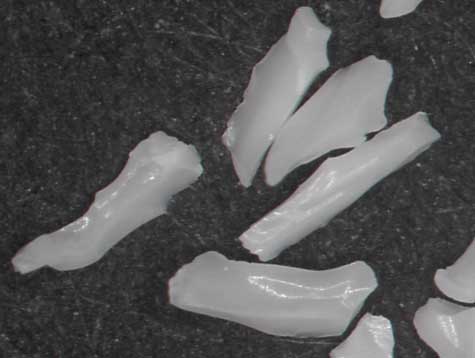
Figure 3
d. Platelet Shaped - Generally found in calcined aluminas. (See Figure 4.)
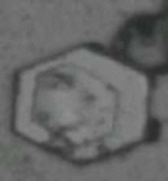
Figure 4
e. Extreme Shapes - A variety of highly unusual shapes are possible through different manufacturing processes for specific applications. Figure 5 shows one of these, extruded abrasives.
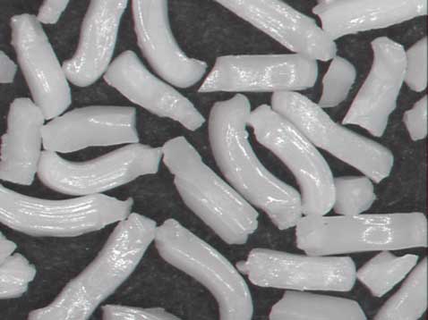
Figure 5
3. Heat Treatments
Heat treatments are often applied to Brown Aluminum Oxides. These may be either high heat or low heat; both enhance toughness, high heat more so than low heat. High heat treatment imparts a bluish color to the grain. Low heat is used to improve cleanliness and capillarity. Uses of heat-treated abrasives include grinding wheels, coated abrasives, and specialized industrial applications.
4. Surface Treatments
A. Silane Treatments - Generally applied to enhance bonding of the abrasive grains to organic resins or epoxies. Applications include grain used for grinding wheels and industrial uses.
B. Projectivity Enhancing Treatments - A variety of coatings can be applied to abrasive grain for the Coated abrasives industry. These coatings enhance the electrostatic properties of the grain to improve projection during the making of sandpaper. (Grain on a conveyor belt passes through an electrostatic field. It "jumps up" or projects onto a sandpaper belt containing a resin. The electrostatic field polarizes each grain so that elongated ends stick up and improve cutting ability.)
C. Iron Oxide Coatings - Applied to improve bonding to resins for grinding wheel and sandpaper applications.
D. Others - Other specialized treatments may be applied to improve "wetability", flowability, suspension in water or oil, or to improve other characteristics. Please Note: This is a very general report which does not include all applications.
Please Note: This is a very general report which does not include all applications.
Manufacture of Abrasives
Most Common Methods
All abrasives contain particles with a range of sizes. In general, the more uniform in size the abrasive, the more expensive and difficult it is to manufacture. Sizing or grading refers to making the particle sizes within an abrasive more uniform so that the majority of the particles fall within a given range of sizes.
There are three ways this can be done: The abrasive particles themselves can be made smaller until they are all the same very small size; the abrasive particles can be joined together to make larger particles of a desired size; or the particles can be sorted into different sizes. Most abrasive manufacturing uses some combination of these methods to obtain particles of the desired size range.
Furnacing Aluminum Oxide: The Electric Furnace Process
Fused Aluminum Oxide is produced in an electric furnace. For brown aluminum oxide, the furnace is mainly charged with bauxite. Additives are included to increase the amount of alumina and toughen the abrasive qualities of the end product. At approximately 2000C, the furnace charge melts and fuses together.
Typically, a brown aluminum oxide furnace produces two products. Some of the additives included in the furnacing combine with the impurities in the bauxite to produce ferrosilicon. This is much heavier than aluminum oxide and settles to the bottom of the furnace.
When the process is complete, the furnace is tilted slightly, pouring the molten alumina into a pot. The pot is allowed to cool. After cooling, the crude ingot is removed from the pot, crushed and sized. The ferrosilicon is removed from the furnace by tilting the furnace fully to remove the heavier material from the bottom. After cooling, it is also crushed and sized.
For the production of white fused alumina, white alumina ore is used as the raw material. It has been refined from bauxite by the Bayer process, which removes almost all impurities. No additives need to be included in the furnace charge, and the operation is the simple electric furnace fusion of the white alumina ore. Pouring, cooling, crushing, and sizing are the same as for brown fused alumina.
Furnacing Silicon Carbide
Silicon Carbide is formed through an electro-chemical vapor phase reaction which takes place above 15000C. Silicon oxide (sand) and coke are mixed together and an electric current applied to the mix to bring it to the required temperature for the formation of silicon carbide. After the reaction is complete, any remaining unreacted graphite is removed, and the silicon carbide pile (fused into a solid mass) is crushed for removal in layers. Generally, the innermost portion of the pile has the purest silicon carbide. After initial crushing, further size reduction and classification are as for fused aluminum oxide.
Size Reduction
Fused abrasives, as discussed above, must undergo size reduction typically by crushing before being classified into sizes. The equipment used includes jaw crushers, gyratory crushers, hammermill crushers, and roll crushers. The goal is to crush the large ingots of fused material into smaller particles.
Abrasives such as calcined alumnium oxide are typically agglomerated after furnacing. These agglomerates undergo size reduction of a different sort, meant to separate the agglomerates into individual crystals. This is typically accomplished by milling, for example in a ball mill or jet mill. In a jet mill, streams of material are shot into each other at high pressure. In a ball mill, the abrasive is added to the grinding media in a closed container which is then agitated (by vibration, rolling, etc.).
Milling may also be used to reduce all the particles in a material to a given size or smaller. Because grinding is selective (larger particles receive more force than smaller particles), size reduction tends to proceed to a given size and then slow down, making it possible to obtain a reasonably tight size distribution.
Size Classification
After size reduction, the material is separated into discrete size ranges. This is accomplished by a variety of means, including most prominently screening, air classifying, and water classifying.
In screening, the material to be separated is passed over a series of screens with decreasing opening sizes. At the first, coarsest, screen, most of the material passes through, with only the largest particles retained on the screen and eventually collected. At the second screen, the next coarsest fraction is removed, and so on.
In air classifying, the material is blown across a series of openings. The coarsest particles fall first; the finer particles fall later. Thus, size separation is achieved.
There are two main forms of water classification, fractional sedimentation and elutriation. In fractional sedimentation, the material is mixed with water and a dispersing agent to allow for discrete settling. The agitation ceases, and the material begins to settle. After a given period of time, all particles over a given diameter will have settled at least to a given depth. The material and liquid above that depth are then removed, and the material removed from the liquid, while the remaining material is then remixed for further gradual material removal.
In elutriation, the same principle applies, but the column of water in which the material is settling is itself moving at a fixed rate (as more water is added near the bottom of the column). Particles small enough to settle more slowly than the column of water is moving upward are floated off and collected.
Sintering
In some cases, it is desired to agglomerate smaller abrasive particles together into larger chunks. This is frequently done by sintering. In sintering, the abrasive is mixed with a quantity of another material which has a lower melting point than the abrasive. The mixture is then heated beyond the lower melting point. This causes the mass to adhere together. The sintered mass can then be formed into granules of the desired size and shape, and allowed to cool.
Characterization of Abrasives
Abrasives are most commonly used to remove part of the surface of some material, called the substrate or workpiece. This removal is called abrading. The abrading occurs by rubbing the abrasive under some pressure against the surface to be abraded. To effectively abrade, the abrasive must be harder than the material being abraded. The rate at which the surface is removed, and the smoothness of the abraded surface, depend upon a variety of characteristics of the abrasive and the substrate. Of these, the most important is the size of the abrasive particles. When we speak of characterization of abrasives, we frequently mean describing the particle size distribution. If everything else is equal, larger particles abrade more rapidly, and leave a rougher surface, than smaller particles. Thus, it is important for the user to know approximately the size of the abrasive they are using. Abrasives with relatively large particles are called coarse; those with smaller particles are called fine. These are, of course, relative terms. It is more correct to call one abrasive coarser or finer than another.
All abrasives contain particles with a range of sizes. In general, the more uniform in size the abrasive, the more expensive and difficult it is to manufacture. Sizing or grading refers to making the particle sizes within an abrasive more uniform so that the majority of the particles fall within a given range of sizes.
There are three ways this can be done: The abrasive particles themselves can be made smaller until they are all the same very small size; the abrasive particles can be joined together to make larger particles of a desired size; or the particles can be sorted into different sizes. Most abrasive manufacturing uses some combination of these methods to obtain particles of the desired size. However, there is no such thing as an abrasive in which are all the particles are the same size, down to the number of molecules for example in each particle.
Luckily, there are few if any applications which require all the particles to be the same size. A few very demanding applications require all the particles to be so close in size it is difficult to distinguish one particle from another, even with very sophisticated equipment. Less demanding applications may find no difference in performance between an abrasive with a very narrow range of sizes and one with a much broader range.
We describe the range of particle sizes within an abrasive by means of a particle size distribution. Thus, we may say that all of the particles are larger than ten microns in diameter, half of the particles are larger (and half smaller) than 30 microns in diameter, and none of the particles are larger than 60 microns in diameter. But the user of the abrasive may want to know if, having used this abrasive, they later use an abrasive in which all of the particles are larger than 11 microns, half are larger than 29 microns, and none are larger than 58 microns, they can expect it to perform the same.
To help answer this question, within the various types of abrasives discussed above, various sizes or grades of abrasive are available. These sizes are standardized within the abrasives industry. For example, while the particle size distribution of individual batches of ANSI 100 grade will vary, they will all meet a set of particle size distribution criteria. There will be few if any particles over 212 microns in diameter, no more than 20% of the abrasive will be made up of particles over 150 microns in diameter, etc. Standard sizes covered by various national and international standards are shown in Exhibits 2 through 7.
Many individual abrasive manufacturers have also developed their own sets of size ranges; in general, the designations used have some connection to the size of the abrasive particles. The individual manufacturers can generally relate these sizes to those covered by one of the national or international standards.
Of course, in addition to size, other characteristics of the abrasive, such as the bulk density, capillarity, pH, friability, surface area, and free iron and other chemical content may be crucial to appropriate performance in various applications. Development and updating standardized ways to measure such characteristics is the main focus of the Standards Committee. These standards, supported by the UAMA, provide the basis for manufacturers to supply globally. For a list of grain characterization standards supported by the Standards Committee, see Appendix 2.
How Big Is This Particle?
When we talk about the size of an individual particle, what do we actually mean? Consider the particle shown in Exhibit 1. (The top left view and right view are the same at different levels of magnification.) Viewed from the "top", it looks like the particle on the right. Viewed on edge, it looks like the particle at the lower left. And viewed on edge from one end, it might look similar to the particle at the upper left. If we define the size of a particle as the mean diameter of the largest surface, this particle would be the diameter of the larger circle shown. If we define it as the average diameter of all its sides, it would be considerably smaller. If we define it based on its volume, it would be another value still.
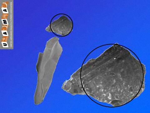
Exhibit 1
How we define the size of a particle has everything to do with how we measure it.
Methods of Measurement
Abrasive sizes are broadly broken into two groups, macrogrits (also called "screen sizes") and microgrits (also called "sedimentation sizes"). This division is due to the different methods of size measurement traditionally used. (Some modern methods of particle size measurement may be used on either type of material, as discussed below.)
Screen Sizing Using Test Sieves
Suppose we wished to make sure that none of the particles in our ANSI 100 grade abrasive were over 212 microns in diameter. We could look at a large volume under a microscope, checking to make sure there were no oversized particles; or, we could screen it through a sieve with openings 212 microns in size, hoping it all passed through. This latter method, using sieves with known opening sizes to see how much abrasive can pass through under given conditions, has long been the industry standard. These measurements are performed with specially produced and controlled test sieves.
Test sieves are woven wire or electroformed screens or perforated metal pans that are used for testing and sifting. Of these, woven wire sieves are most commonly used for testing materials to ensure they meet a designated particle size distribution. Woven wire test sieves are constructed by placing wire cloth between two suppressed die formed frames. Stainless steel or brass is generally used in the construction of both the frame and woven wire mesh that performs the sieving. These devices are widely used in various types of laboratory particle size analysis.
Test sieves are manufactured to standardized requirements; the specific standard used depends on where it is manufactured, and the type of sieve. In the United States, ASTM E11 covers the requirements for design and construction of woven wire cloth test sieves. European sieves are manufactured to ISO Standard 3310-1. Electroformed sieves are manufactured in the United States to ASTM E161, while perforated plate sieves are manufactured to ASTM E323, or British Standard BS140-1. All of these standards specify a number of properties to which any rated test sieves must adhere. These ratings include acceptable opening sizes, opening dimensions, maximum number of allowable openings in each test sieve, and in the case of woven wire sieves, nominal wire diameter.
Sieves are available in a number of quality levels, with the precise nomenclature used varying by manufacturer. Commonly used terms include certified, inspection, matched, calibrated, matched and calibrated, and midpoint. Certified or inspection sieves are the most widely used. They are manufactured to a national or international standard and come with a certificate of conformity. It is also possible to obtain pairs of sieves that have been manufactured and tested to match each other, and sieves with a test certificate which gives the range of tolerances and measurements taken.
MacroGrits
Macrogrits (sizes 4 to 220 or 240, also called screen sizes or sieve sizes) are traditionally measured using test sieves. The particles in these sizes range from less than 45 microns to up to 8mm (8000 microns). A range of particles is allowed to be present in a given size, with a maximum coarse limit and a minimum fine percentage. (For most sizes, no more than 3% of the abrasive by weight is allowed to be finer than the fine limit.) To determine the particle size distribution of a material, a stack of sieves with known openings is prepared, with the sieve with the biggest openings on top, the smallest on the bottom. A known weight of the material to be tested is placed on the top sieve, and the stack is shaken or tapped to sift the material through the sieves. (The devices most commonly used to tap or shake the sieves during testing are the Rotap and the CAMI sifter.) Particles too large to pass through a sieve are retained on top of it. After a given time, the stack is disassembled and the material retained on each sieve is removed and weighed. So, if the top sieve on the stack has an opening of 200 microns, and all the material has passed through it, we know that the material contains no particles larger than 200 microns. If the next sieve has an opening of 170 microns, and 10% of the material is retained on it, we know that 10% of the material is from 170 to 200 microns in size. Thus, with the appropriate sieves, we can obtain a complete measurement of the distribution of particle sizes within it.
Calibration of Test Sieves
The problem of how to correctly calibrate a sieve lies in the high levels of precision required, combined with the relatively imprecise nature of the sieves themselves. The processes by which the sieves are made give rise to variations in both the average opening size and the range of sizes in a given sieve. For example, according to ISO 3310-1, the maximum permitted opening on a 63 micron sieve is 89 microns. While it is rare to find such discrepancies in practice, should they occur there could be serious consequences. It is therefore critical that the effective opening size of a sieve is known, and sieves should be calibrated on a regular basis.
Since it is not possible to adjust how a test sieve measures, calibration is a verification procedure based on sieving performance on a known material compared to a set of master sieves of known accuracy. The known material used is a standard sand (see Appendix 3). Standard sands are manufactured so that a set percentage (generally around 50%, but specified in the documentation accompanying the sand) is retained on a sieve of a given size, when measured under specified conditions (described in ANSI B.74-12-2001; see Appendix 2.) To be used for grading abrasives, the sieve must retain the required percentage, plus or minus a small margin of error, which may then be taken into account when evaluating materials.
Standard sizes have been developed both for the sieves and for the abrasives they measure. For the test sieves, these are given in the various standards mentioned above. For the abrasives, they are given in several of the standards listed in Appendix 2. These sizes are discussed in more detail below, and in Exhibit 1.
Test sieves have long been the single most important tool for grading abrasives and many other dry materials. This is not to say they are without their drawbacks. Uniform size testing of abrasives by Rotap has long been a problem for the industry. This is due to variability in the manufacture of test sieves and changes in the specifications of wire sieving cloth, as was discussed above. It was these problems that led to the development and implementation of standard sands for sieve calibration. As of now, test sieves remain the only standardized method for measuring macrogrit distribution. The standards committee is actively investigating alternative methods, including laser diffraction analysis and ,photosedimentation and image analysis (see below). However, no standards have been developed yet for macrogrits using these methods.
Microgrits: Sedimentation
Microgrits (also called sedimentation sizes) are defined as sizes corresponding to 240 or 280 (approximately 60 microns in size) and finer. For many years, the standard method of measuring these sizes was through sedimentation using Stokes' Law. In lay terms, Stokes Law says that the bigger the particle, the faster it settles in a liquid. If you know the apparent specific gravity of the material, and the density and viscosity of the liquid, and the distance it settles, and the time it takes to settle, you can calculate how big the particle is. This is applied in practice through the use of a long column filled with alcohol (called the settling medium) at a known temperature, sitting inside a larger tube filled with water to maintain the alcohol at the correct temperature. At the bottom of the tube is a smaller graduated collecting tube. This apparatus is called a sedimentometer, or sedimentation tube. The material to be tested is pre-wet, then placed in the settling medium at the top of the tube, and the time recorded. When the first material reaches the collecting tube, the time is recorded. As the material reaches the various graduations in the settling tube, these times are recorded, until all the material has settled. Based on the total height of material in the tube, say 25mm, we know that the time required for the material to reach 12 mm represents 48% of the cumulative volume percentage. If it reached this height in 8 minutes, that means 48% of the material is 28.2 microns and coarser in size. If the 2mm height was reached in 4 minutes, that means 8% of the material is 39.8 microns and coarser. (These figures are taken from material in ANSI Standard B74.10, for aluminum oxide. Times for materials with a different density, such as silicon carbide, are different.)
Obviously, this is a very time-consuming method. Very fine materials may take 24 hours or more to settle completely. Only one test per sedimentation tube can be run at a time. During the test, the operator must constantly tap the settling tube to insure even packing and level settling. For these reasons, this method has largely been replaced over the past 30 years by other methods of measurement. However, it is still in use in some companies, and the standard governing its use remains in effect.
Microgrits: Electrical Resistance Method
Beginning in the 1970's, some abrasives companies began using electrical resistance to measure microgrits. The principle of electrical resistance measurement is that a particle will cause a change in the strength of a current proportional to the volume of the particle. The standard apparatus used for electrical resistance measurement is the Coulter Counter, which has gone through a variety of model numbers over the years. (A competitive product using the same principle is the Elzone.) For ease of reference, electrical resistance methods will be referred to simply as "Coulter", recognizing that Coulter Corporation makes a variety of test and analytical equipment and that other companies manufacture electrical resistance measurement equipment.
All "Coulter" instruments have the same basic design. (A diagram is provided in ANSI B74.10-2001.) A reservoir is filled with filtered electrolyte solution (generally water with 1%-4% salt content). A sample beaker is filled with the same solution in which the material to be tested is suspended. The solution is pumped into a hollow glass tube (called the aperture tube) with a small hole of known diameter (the aperture) in the end. The tube is immersed in the sample beaker. Inside the tube is an electrode, and outside the tube, in the sample beaker, is another electrode. During analysis, a vacuum pump pulls solution from the sample beaker through the aperture into the tube and eventually to a waste container. A current is passed between the electrodes. As the solution passes through the aperture, any particles present cause changes in the current proportional to the volume of the particle. The instrument records these changes as representative of particles of various sizes, based on a calibration value for the aperture tube in question. (The calibration value is obtained by measuring latex spheres of known size.)
The instrument is meant to be run with a variety of sizes of aperture tube, based on the particle sizes to be measured. This is because each aperture tube can measure only a small range of particles, nominally ranging in size from 2% to 60% of the aperture diameter. Thus, a tube with a 100 micron diameter aperture is capable of recording particles from 2 to 60 microns. While there is a method of running samples with a wider distribution, it is complicated and time-consuming.
The sizes registered also present a problem. The Coulter cannot take particle shape into account, and registers only particle volume. To translate this into diameter, the instrument assumes all particles are spheres, and gives a particle's diameter as the diameter of a sphere of the same volume (spherical equivalency). For blocky or cubic material, this represents a small distortion. For sharp or platelet material, the distortion is larger. In general, non-spherical material will be measured as finer on the Coulter than it is by sedimentation method. The degree of the offset will be roughly proportionate to the aspect ratio of the material. For example, a calcined alumina with an aspect ratio of 5:1, which has an average particle size of 12 microns on a sedimentometer, will have an average size of approximately 7 microns on a Coulter.
Other Methods of Measurement
Photosedimentation
This method is widely used in Europe, less so in the United States for abrasives. It relies on Stokes Law (as sedimentation does) with the particles centifuged in a liquid and the size determined by the time it takes particles to move from the center of a disk to photodetectors on the outside. Used for microgrits down to and including sub-micron particles.
Microscopy-Based Analysis
Varying methods use microscopy with detectors to measure particle sizes on a sample. The principle is the same as looking at particles in a microscope and sizing each to determine the distribution of the sample. This method is not in wide use yet for particle size distribution measurements of abrasives. It does have the potential to measure both macrogrits and microgrits simultaneously across a wide range of particle sizes.
Laser Diffraction Analysis
Gaining in popularity, this method passes the particles in front of an optical detector on which a laser bean is projected. The particles diffract (bend) the laser in an amount proportionate to their size. Beginning to be more widely used by abrasives manufacturers, but not yet subject to any standards in the United States. The size results tend to lie between sedimentation and electrical resistance measurements for microgrits. A very versatile method, newer instruments are also capable of measuring most macrogrits. However, because of the wide size ranges involved, poorer discrimination of very narrow size ranges is provided compared to electrical resistance. Multiple companies manufacture these instruments, making potential standardization problematic.
Time of Flight
Used primarily for fine powders, the particles are suspended in an aerosol beam. The analyzer measures the time of movement of the particles between two points of known distance apart.
As the preceding survey indicates, the variety of methods of particle size analysis available, not to mention possible variations within each method, make standardizing of methods and sizes an on-going challenge. ASTM E-1919-00 covers particle characterization methods, particularly particle sizing.
Variability Within and Between Testing Methods
Regardless of the size of the abrasive being measured, the results obtained will depend not only on the general method being used but also on the particular instrument chosen. In some cases, very good agreement can be had between instruments using the same principle of measurement (such as two instruments using laser diffraction) IF all other parameters which can affect the measurement are kept as identical as possible. In other cases, wide variation in results can be obtained even by using the same method and instrument. For example, if two different Rotaps using two sets of test sieves are used to measure the same material, differences as large as five percentage points in the amount retained on an individual sieve are common. This is due to variability between the Rotaps, variation between the sieves, and sample to sample variation. If a non-Rotap sieve shaker is used, even greater differences are likely.
In the case of other types of measurement, where variations in sample preparation, instrument settings, ancillary equipment, and operator technique can have a substantial affect on the results, the differences can be substantial, raising the issue of whose results to trust. When two totally different methods are used (for example laser diffraction by a supplier and electrical resistance a customer), the results of course cannot be compared at all.
National and International Size Standards
Macrogrits
Despite these problems, standards have been issued for full ranges of macrogrit and microgrit sizes by ANSI, FEPA, and JIS. (ANSI is of course the American National Standards Institute; FEPA is the European Federation of Abrasives Producers; and JIS is the Japanese Standardization Organization.) For macrogrits, these standards are all but identical, and differ only in a few of the sizes covered and the range of applications covered. ANSI standard B74.12-2001 gives two separate specifications, one for abrasives to be used for grinding wheel and general industrial applications, one for abrasives to be used for blasting. For the sizes covered, the only difference is material used for blasting need not be as tightly sized. Comparing ANSI B74.12-2001 with FEPA 43GB-1984R1991 and JIS R6001-1987, the size requirements for sizes defined are identical. FEPA includes two sizes, F22 and F40, not covered by ANSI or JIS. JIS does not cover the four coarsest sizes, 4, 5, 6 and 7, covered by ANSI and FEPA.
ANSI B74.18-1996, currently under revision, covers coated abrasives. These sizing requirements are quite different from those for bonded and loose abrasives. (For brevity, the differing standards will be referred to as "bonded" and "coated.") In general, it is entirely possible that any particular abrasive that meets the requirements for a coated size will meet the requirements for the same bonded size (that is, an ANSI bonded 180 may also be acceptable as an ANSI coated 180), and vice-versa. It is also entirely possible that a FEPA F120 (bonded) will not meet the requirements of a FEPA P120 (coated), and vice-versa. This is because the standards specify different sieve sizes to be used for testing, allow or require different percentages of retained material on the various sieves, and in general state the requirements in a manner which frustrates direct comparison of the sizes.
Without entering into a detailed comparison of the standards, which the interested user is encouraged to do, one example will hopefully suffice. For FEPA P80 (coated), FEPA GB43-1991 requires all of the material to pass through a 355 micron sieve, and a maximum of 3% be retained on a 255 micron sieve. For FEPA F80 (bonded), FEPA 42GB-1984R1993 requires all the material to pass through a 300 micron sieve. There is no requirement with regard to a 255 micron sieve, and up to 25% of the material may be retained on a 212 micron sieve. Clearly, a single abrasive with no particles over 255 microns would meet both these standards. But an abrasive with no particles over 355 microns, 1% from 300 to 355 microns, and 2% from 255 to 300 microns would meet the coated standard and fail the bonded one. An abrasive with no particles over 300 microns but 4% from 255 to 300 microns would meet the bonded standard and fail the coated one.
With regard to ANSI B74.18-1996, direct comparison is even more difficult, since the standard in general does not specify what percentages may or must be retained. Instead, the sieves themselves are first calibrated with a standard sand (see Appendix 3). The requirements for the material to be tested are then expressed in terms of the performance of the sieve with regards to the standard sand. Thus, for a coated ANSI 120, the maximum percentage allowed to be retained on a 133 micron sieve is 1.2 times the percentage of standard sand retained on that same sieve. The 133 micron sieve must have retained from 9.9 to 17.9 percent of the 120 standard sand. That same sieve is then used as a fines control sieve for coated 100 grade. The percentage of material which passes through that sieve must be within +10%/ -7% of the percentage of the 100 grade standard sand which passed through it.
In comparing coated with bonded macrogrits, the most that can be said is that the sizes are approximately the same, but the specified requirements differ sufficiently to require individual appraisal of batches of material.
Exhibits 2 and 3 show the approximate size range of the standard sizes of macrogrits by FEPA, ANSI, and JIS requirements. For all sizes, the standards require that at least 70% to 85% (depending on the size in question) of the abrasive pass through a coarse control sieve and at least cumulatively 60% to 70% of the abrasive be retained on two or three finer sieves. The size range for each size given in Exhibits 1 and 2 is from the opening of the finest sieve to the opening of the control sieve.
Thus, for ANSI grade 80 (FEPA F80, JIS 80), a total of 65% of the sample must be retained on sieves with openings of 150 and 180 microns. At least 75% of the size must pass through a sieve with an opening of 212 microns. The range shown for size 80 is thus 150 to 212 microns: at least 65% of the sample, including the median size, will fall within this range.
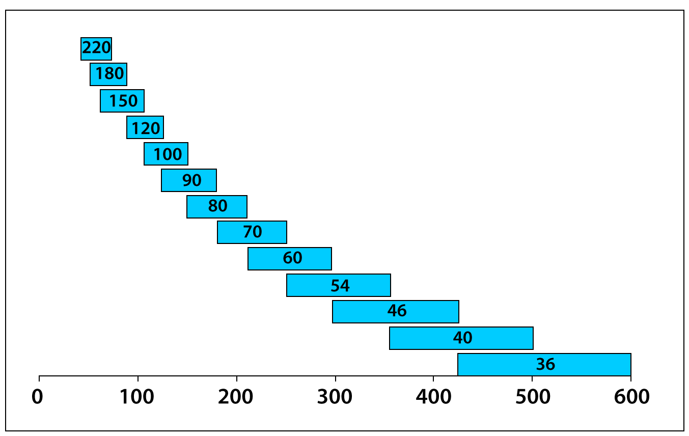
Exhibit 2
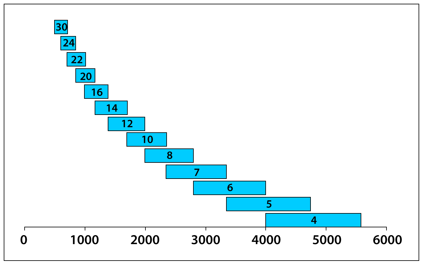
Exhibit 3
MICROGRITS
Comparison of standards for microgrits is not as straightforward. ANSI standards for coated and bonded grains differ substantially, as do the FEPA standards for coated (called "FEPA P") and bonded (called "FEPA F") grains. The JIS standard is also quite different. For the most part, the standards specify a) a minimum value which 94% of the abrasive must be coarser than, b) a maximum value that 97% of the abrasive must be finer than, and c) the range in which the midpoint must fall. Exhibits 4, 5 6 and 7 show the required midpoint ranges when measured by electrical resistance as specified in the various standards. Exhibits 8, 9, 10 and 11 show the full size range (from 3% to 94%, 95% for FEPA P) of the same sizes. The relevant standards are ANSI B74.10-2001 (bonded and loose grain, shown as "ANSI" in the exhibits), ANSI B74.18-1996 (shown as "Coated" in the exhibits), FEPA 42-D-1984R1993 and ISO 8486 (for bonded and loose grain, shown as "FEPA" in the exhibits), FEPA 43-GB-1983R1993 (for coated abrasives, shown as FEPA P in the exhibits), and JIS R 6001-1987 (shown as "JIS" in the Exhibits). In all cases, the shaded area under the size label shows the size range of interest. Where the specifications are identical (for example, for JIS and ANSI-Coated, sizes 4000 and finer), the label shows both sizes. ANSI coated sizes 240 to 500 are not specified by electrical resistance measurement in ANSI B74.18-1996, and thus were not included in the exhibits. In general, they are close to the JIS sizes. FEPA P (coated) microgrits are not specified by electrical resistance, but by sedimentometer. The values given in the exhibits are based on electrical resistance equivalents of the sedimentometer values. An important point to remember about the microgrits is that the same size number may refer to very different sizes, depending on the standard being used. Thus, a JIS 600 has an average particle size of 18.5-21.5 microns. A FEPA F600 has an average size of 8.3-10.3 microns.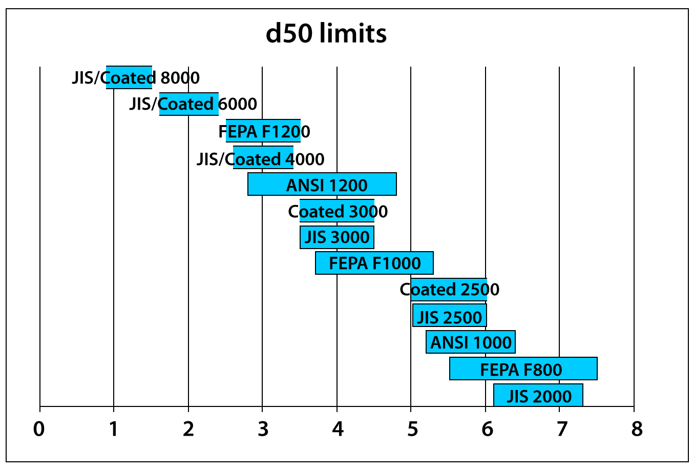
Exhibit 4
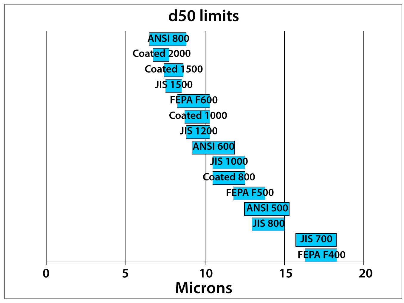
Exhibit 5
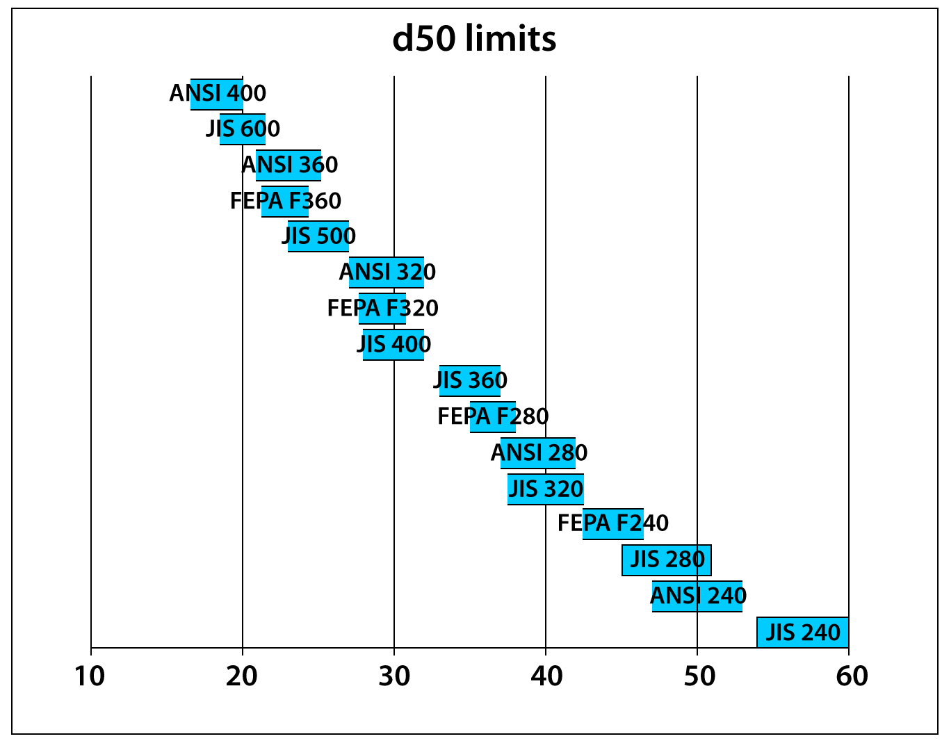
Exhibit 6
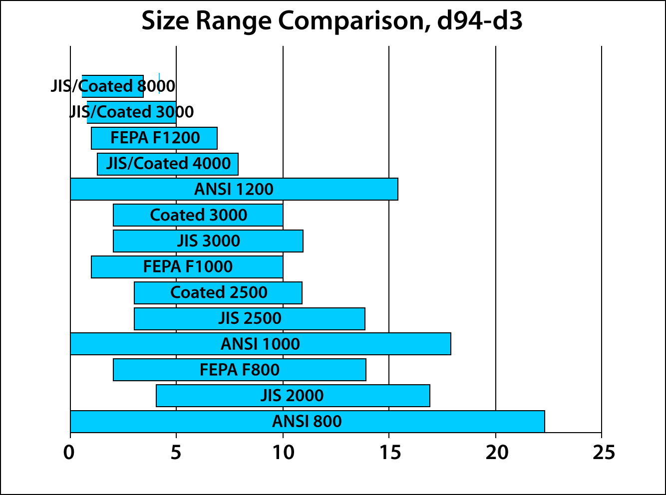
Exhibit 7
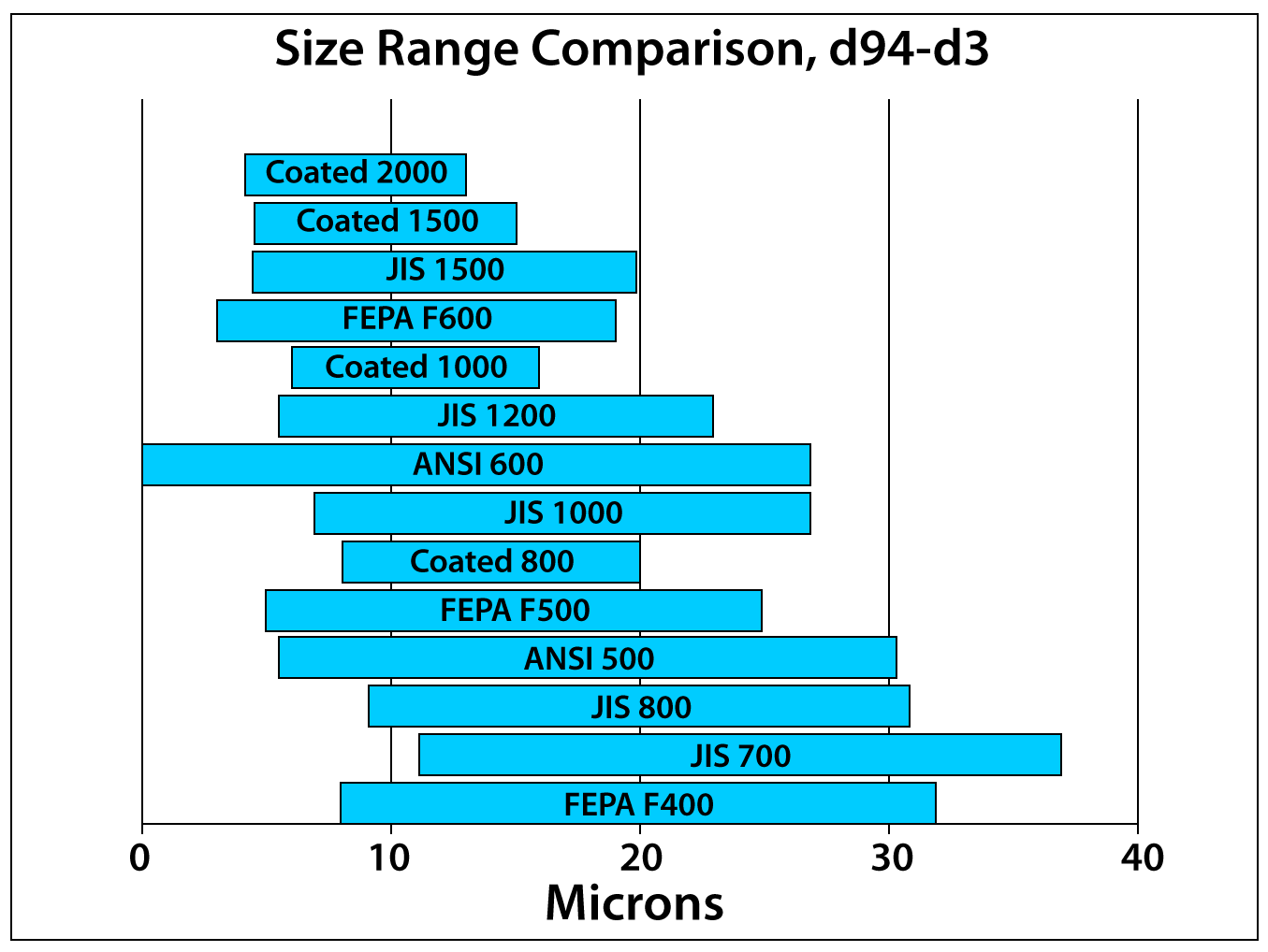
Exhibit 8
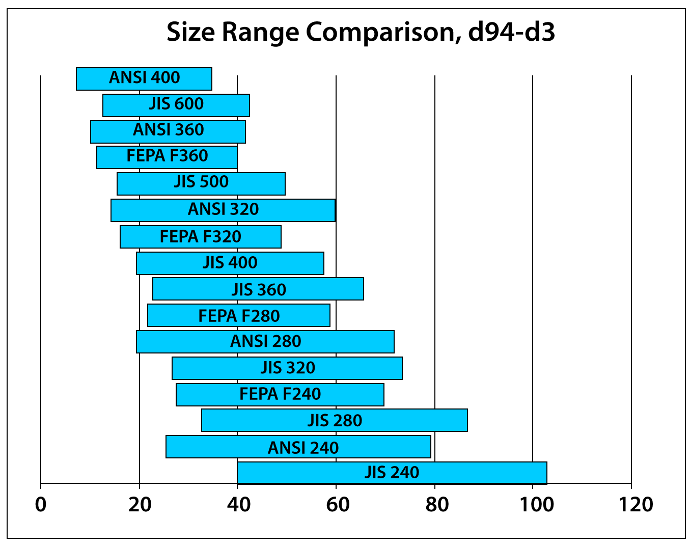
Exhibit 9
Superabrasives
As noted above, some manufactured abrasives, commonly diamond and cubic boron nitride (CBN), are characterized as superabrasives due largely to their extreme hardness. These are used in a variety of demanding high-tech applications. Standard sizes of these materials and approved testing methods are defined in ANSI B74.20-2004, currently under pre-publication formatting as of this writing. In general, standard sizes for these materials are defined as a size range (e.g. 1-2 microns, 6-12 microns). The standard specifies that materials in these sizes must include at least 90% of the particle size distribution within the size ranges specified (maximum of 5% each above and below the range). For example, for a 1-2 micron size, at least 95% of the sample must be above 1 micron in size, and no more than 5% of the sample may be over 2 microns in size. The sample's average size must be near the center of the desired distribution (1.28-1.72 microns for a 1-2 micron material). Additionally, the coarsest particle detected must be below a maximum limit (e.g. 6 microns for size 1-2, 20 microns for size 6-12). ANSI B74.20 also describes a variety of methods that are commonly used to characterize the particle size, including a number discussed above (such as electrical resistance, direct microscopy, laser diffraction, and photosedimentation) and a few methods unique to characterizing extremely fine particles (such as photon correlation spectroscopy). For further details on these materials, relevant calibration standards, and an excellent detailed discussion of methods of measurement, please refer to B74.20.